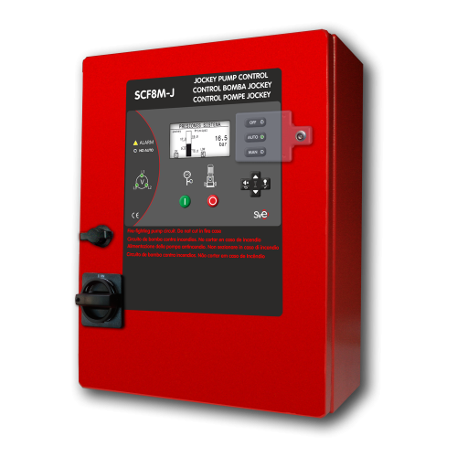
Controllers for high power electric Jockey Pumps
SCF8M-J controllers, are complete user friendly and configurable instruments, useful for automatically operate up to 75 kW Jockey pumps in any environment
SCF8M-J controllers automatically start and stop Jockey pumps depending on the system’s demand; protect them by means of the connected and controller-generated alarms, visualize the most relevant values and informations, also manage the communication of the operator and both the contour elements and the remoted manned centre.
MAIN FEATURES: SCF8M-J
Medium size Jockey Fire Pumps controllers: EN 12845 / NFPA 20
Nº STANDARDS & TECHNICAL RULES 1 Standard EN 12845 Ed.2016 2 Standard NFPA-20 3 Standard UNE 23500 Ed.2018 4 Standard UNI 10779 Ed. 2014 5 Standard LPC TB210 / FOC 6 Standard IEC 61439-1 Ed. 2011 Low-voltage switchgear and controlgear assemblies 7 Tech. Rule CEPREVEN R.T.1-ROC Ed.2004 8 Tech. Rule CEPREVEN R.T.2-ABA Ed.2006 Nº RANGE OF MODELS (according to type plate) 1 Incoming line voltage 400 V AC / 230 V AC 2 Mains frequency 50Hz / 60 Hz. 3 Jockey pump size Up to 75 kW 4 Motor starter type DOL / λ-Δ according to the motor power Nº CONSTRUCTIVE FEATURES 1 External enclosure IP65 Protected from total dust ingress (NEMA 4) 2 Impact rating: IK10 (except for display) 3 Fireproof grade: Fire extinguishes <30s 4 Display Transflective: Visible under direct sunlight 5 Wiring Halogen free 6 Fireproof: RZ1 according to EN50200 (830ºC for 90min) 7 Pump room temperature 20 ºF to 122ºF (-5ºC to 55ºC) 8 Isolation rating between phases 500 V AC 9 Isolation rating between phases and ground 2.500 V AC 10 Isolation impedance between phases and ground 2 MΩ 11 Earthing system TT system (neutral and earht connected separatelly ) 12 Electromagnetic environment CEM-1 Nº MEASURING INSTRUMENTS IN THE DISPLAY 1 System 3 Voltmeter: voltage for every phase L1-L2-L3 (RMS) 2 1 Mains frequency meter 3 1 pump rotation/phase rotation 4 1 Manometer pump discharge pressure ( pressure sensor required with 4-20 mA signal) 5 Jockey pump 1 Ammeter: pump current (RMS) 6 1 Active power in KW (RMS) 7 1 Power factor (Cos φ) 8 Controller 1 Voltmeter: Internal voltage 9 Controller 1 Voltmeter: back-up battery voltaje Nº PUMS & SYSTEM PROTECTION 1 Voltage loss 2 Normal power phase reversal 3 Normal frequency loss 4 Jockey pump protection trip 5 Controller power loss 6 Low water reservoir tank 7 Low back-up battery voltage 8 Main pump pressure switch open circuit 9 Low power factor jockey pump 10 Under-current Jockey pump 11 Overload Jockey pump 12 Pressure sensor fault Nº COMMUNICATIONS & SIGNAL TRANSMISSION 1 micro USB Port Boot loader for firmware upgrading 2 SAF8M (control panel PLC ) configuration 3 PC monitoring: Pump and installation general condition 4 Pendrive data down-load: Events log / Pressures log 5 ETHERNET (Optional) SAF8M (control panel PLC ) configuration 6 PC monitoring: Pump and installation general condition 7 RS485 port (Optional) SAF8M (control panel PLC ) configuration 8 PC monitoring: Pump and installation general condition 9 Voltage free contacts :
up to 30 V DC / 0,3 AVoltage loss 10 Pump non automatic mode 11 Fail to start / not discharge pressure 12 Grouped alarmas 13 Pump on demand 14 Pump running Nº LANGUAGES / OTHER FEATURES 1 ENGLISH / ESPAÑOL / ITALIANO / FRANÇAIS / PORTUGUES / DEUTSCH / NEDERLANDSE 2 System pressure meter: Value displayed on digital screen. Selection of demand and stop levels 3 3 operatin modes: OFF/ MAN / AUTO 4 Events log: Historical of 500 events in memory: Downloadable to pendrive 5 Pressures register log: Historical of 16,000 records in memory: Downloadable to pendrive 6 Jockey pump start count & hours and minutes 7 Power elements: Contact breakers in AC-3 / Isolator switches in AC-23


