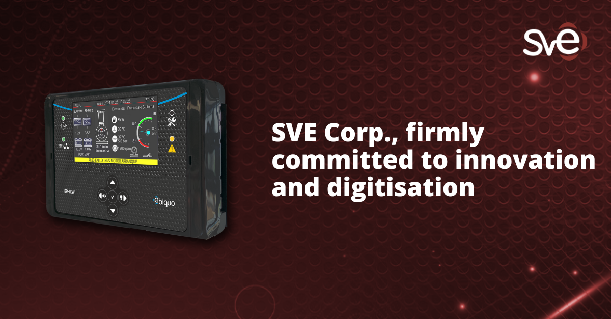
Conducted emission and immunity tests are fundamental to electromagnetic compatibility (EMC) certifications, as they ensure that electronic products do not generate unacceptable interference and that they can operate correctly in electromagnetic noise environments. Their relevance and framing within the certification process can be broken down as follows:
-
What do they assess?
They measure unwanted electromagnetic signals that a device introduces into the power grid or other interconnecting lines. These emissions may affect other devices connected to the same power grid.
-
Basis
- Electrical and electronic products can generate interference through the power supply network or communication lines.
- Noise levels are analysed in the range 9 kHz to 30 MHz.
- The results are compared with limits established in international standards.
-
Relevance
- It is a mandatory requirement for CE certification in Europe and FCC certification in the USA.
- Equipment that generates excessive conducted emissions can cause the following problems:
-
- Communication in the surrounding products (interference in ethernet, RS-485, CAN BUS communications), causing loss of data.
- In audio or video equipment, generating interferences in the transmission, causing unexpected noises.
- In industrial sensor equipment, causing incorrect measurements of the physical measurement being analysed
- On equipment with wireless communications systems, causing data loss.
- Restarting or blocking of equipment in the environment.
- Overheating of equipment and the environment.
- They can cause unexpected tripping of the installation’s protections.
-
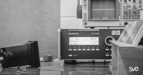
Testing procedure at SVE Corp.
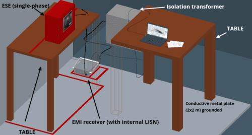
1.- Trial setup
For tests of equipment with single-phase supply, the arrangement is as follows:
For testing equipment with three-phase power supply, the arrangement is as follows:
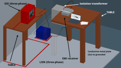
The difference between a single-phase and a three-phase equipment test is that for the latter the AMN has to be external, as the integrated AMN/V-LISN in the EMI receiver is single-phase.
First of all, it is very important to indicate the order or sequence of connection.
We start by connecting the transformer to the mains and without connecting any equipment to it, we switch the isolation transformer ON, then we connect the 7010/02 receiver switched off and if this test is a three-phase test we also connect the LISN L3-32, in both cases the ESE can be connected.
Once the receiver is powered up and switched on, we can configure the required parameters in the PMM emission suite.
The arrangement in which table 1 and table 2 are to be placed in the boxes marked for this purpose.
The position with which the ESE should be placed is as shown in the above illustration; it should be placed in front of the red tape on the table approximately centred so that there is at least 1m from the ESE to the three-phase LISN.
Up to 1.6m of cable shall be considered as part of the ESE. In the event that there is more than 1.6m in length or if 1m and above generates an excessive or surplus dimension for the connection, a bundle of cable must be gathered, i.e. a bundle of cable as close as possible to the ESE and therefore this bundle will remain on top of the table.
As for the other equipment, as can be seen in the image, its position for carrying out the test is indicated. In the case of the PMM 7010/02 receiver, it should be placed on table 2 next to the laptop PC that will record the data obtained by the receiver.
It is important to respect the enclosures with red insulating tape because it has been placed in accordance with the distances required by the regulations. If the enclosures shown in the figure do not exist in the laboratory (either because it has been removed or because it has not been installed), it is necessary to refer to the test instructions and install it according to the distances specified in the regulations (for example, if the equipment must be 0.4 m from the vertical ground plane, the table should be placed (for example) next to the wall and the tape on the table 0.4 m from the boundary).
In addition, stickers (on the red ribbons) have been placed which equipment/objects are placed in each enclosure.
It is also important to have read the test instruction in case there are specifications about the layout of the cables.
The setup to be used for testing the equipment must be selected from the following drop-down list.
2.- Limits
The limits, according to European regulations, are as follows:
| Range (MHz) | Limits (dB μV) | |
| Quasi-peak value | Mean value | |
| 0.15 a 0.5 | 66 a 56 | 56 a 46 |
| 0.5 a 5 | 56 | 46 |
| 5 a 30 | 60 | 50 |
This chart corresponds to UNE-EN IEC 61000-6-3 (2021) table 4 – Requirements for conducted emissions; H-23 PDf.
Or, represented graphically:
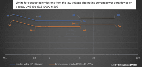
In order to ensure compliance in the external laboratory, it must be ensured that the measurements taken are below the limit by 3 dB μV.
The following points should be taken into account:
- At transition frequencies the lower (more restrictive) limits apply.
- If the limit value varies over a range, its variation is linear in relation to the logarithm of the frequency.
- Checks should be made using both detectors, but a peak detector may be used instead.
- Cables up to 1.6 m are considered part of the ESE.
-
Challenges and resolution strategies
- The main difficulties that can be expected in certification dynamics are the following:
- Proper configuration of the test setup.
- Appropriate choice of measuring equipment.
- Knowledge of testing regulations.
- Interpretation of results and diagnosis of faults if they occur.
- Implementation of solutions to faults without affecting the operation of the equipment.
- The most common actions implemented when a team fails the tests may be the following:
- The extent of conducted emissions must be reduced. To do this, the source where the conducted emissions are generated must be found. After locating the source, it is necessary to analyse how to reduce the amplitude of the emissions, which can be reduced by using: common mode filters, differential mode filters, redoing the PCB design, changing the switching frequency, using capacitors and coils to filter the signals, …
- PCB layout optimisation.
- Isolate the points where conducted emissions are generated so that they do not leave the equipment.
- Use EMI filters: common mode filters, differential mode filters.
- Avoid very abrupt switchovers (reduce the slope of the switchover).
- Use ferrites in the switching lines.
- Improve grounding
-
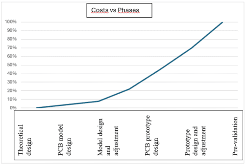
Timing of testing and design
- The best time to conduct conducted emissions testing is during the design and fine-tuning phase of product mock-ups.
- It is very necessary to test at the beginning of the design in order to keep the cost of adjustments lower. According to the design phases: theoretical design, PCB mock-up design, mock-up design and adjustments, PCB prototype design, prototype design and adjustments, pre-validation and industrialisation, the most appropriate time is in the theoretical design and mock-up design.