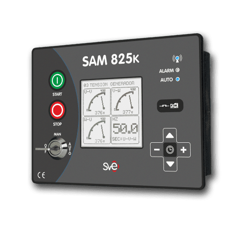
SAM825k controllers are high-performance, complete, automatic, and configurable instruments, useful for controlling generator sets in installations with no electric mains available.
SAM825k controllers automatically start and stop generator sets, protect them by means of the connected and controller-generated alarms, and visualize the most relevant values.
MAIN FEATURES
Nº BASIC FEATURES INDEX 1 Display Graphic/Transflective/3.2″ (outside view) 2 Protection IP65 3 Buzzer Built-in buzzer 4 Safety key Mode selection swiitch: OFF / MAN / AUTO 5 Electrical measurements 3 phases true RMS: V / Amp / kW / kVAr/ KVA 6 Sensors %Fuel / Temperature / Oil Pres. / rpm 6 Communications Canbus/ RS485 / Ethernet / GSM 7 Weekly scheduler clock 4 dayly slots. 8 Fresstanding generators 9 Asociated software Configuration/Control/Monitoring Nº BASIC FUNCTION INDEX 1 Pre-Crank process Starter-Preignition/Gas Ramp/Prelube/Turn on ECU 2 Engine alternator priming D+ 3 Engine start process Crank engine/Bendix 4 Fuel management Electrovalve/shut down solenoid 5 Fuel transfer pump activation Fuel tank level measurement 6 Heating element activation Coolant temperatura measurement 7 Engine idle management Idle/rated speed 8 Cooling water valve management Engine running function 9 Siren activation Externarl optional installation 10 Common alarms output activation Remote communication 11 Configurable outputs Control and warnings 12 Engine-alternator system protection By enabled alarms 13 Man-machine interface using front display 3.2″ graphic/Transflective 14 Communications USB / RS485 / ETHERNET / CANBUS / GSM Nº ELECTRIC MEASUREMENT INSTRUMENTS 1 3 Voltmeters Phase-phase voltages. True RMS: 90V AC – 500V AC ±1% 2 3 Voltmeters Phase-neutral voltages. True RMS: 50V AC – 300V AC ±1% 3 1 Generator phases asymmetry: Δ Vgen % ΔV=(100*(V-Vmean)/Vmean)% 4 3 Ampmeters Generated Amps. True RMS: 0 Amp-1.250 Amp ±2% 5 2 Frequencymeters Mains-Generator: 0Hz-80Hz. Resolution: ±0,1 Hz 6 3 Active power meters KW 7 3 Reactive power meters KVAR 8 3 Apparent power meters KVA 9 3 Power factor meters, Cos φ 3 phases + weighted mean 10 Phases sequence control Generator U / V /W 11 Power imbalances: Δ Apparent power % ΔP=(100*(P-Pmean)/Pmean)% Nº MECHANICAL MEASUREMENT INSTRUMENTS 1 Oil pressure. Sensor or Canbus Range: 0 bar-10 bar ±0,5 bar 2 Coolant temperature. Sensor or Canbus Range: 0ºC – 150ºC ±1ºC 3 Fuel tank level. Sensor Range: 20% – 100% ±5% 4 Engine speed . Terminal W, Pick-Up or Canbus rpm 5 Total fuel consumed. Canbus Liters 6 Instant fuel consumption . Canbus Liter/Hour 7 Current engine torque. Canbus % 8 Torque demand. Canbus % 9 Coolant level. Canbus % 10 Oil level. Canbus % 11 Oil temperature. Canbus ºC 12 Coolant pressure %


